Measuring flow noise
The upper water layers of the sea contain a myriad of small air bubbles created by the breaking waves. When the hull moves through water it will cause a disturbance, and this will generate friction. The friction zone is called the flow boundary layer. All objects sticking out from the hull, or dents in the hull, will disturb the flow and will increase the thickness of the boundary layer. When the flow speed is high, the turbulence can be violent enough to destroy the integrity of the water. Small voids or cavities in the water will occur and this is called cavitation.
The ST90 system is turned on and operates normally.
The ST90 system is in Normal mode, but TX Power is set to Off to prevent transmissions.
The transducer is retracted to its upper position.
If the ST90 system is operated from any other compartment than the bridge, an open two-way oral communication channel with the bridge is required.
Neither tools nor instruments are required. You may however find this equipment useful:
Personal computer
Spreadsheet program
In order to do this test, the ship must be "silent".
- The water must be as deep as possible. Recommended minimum depth is 100 metres.
- There must be no other vessels in the vicinity.
- The vessel must lie still in the water.
- As much machinery as possible must be turned off. It is particularly important to turn off electrical motors, as well as cooling systems and hydraulic pumps that may cause electric noise.
- To prevent interference, all other hydroacoustic instruments must be turned off.
With the vessel in port, the environmental conditions are not satisfactory. In the shallow waters of the port, noise from other vessels, dockyard workers or machinery will cause unreliable test results. If you do this tests in a busy harbour, or with noise sources present, the sensitive receivers will detect all the noise in the nearby waters.
To measure the noise, observe the noise values provided on the Noise page in the Diagnostics dialog box.
If you record all the raw data during the noise test, you can repeat the test later using the replay file.
You may wish to make the noise/speed curve under realistic conditions. This means that all relevant vessels systems are in normal use. If you experience very high noise levels, you may wish to repeat the test with "silent ship" settings.
When the transducer is fully lowered, the speed of the vessel must not exceed the maximum speed permitted for the hull unit. This maximum speed depends on the physical size of the transducer, the mechanical construction of the hull unit, and how far down the transducer has been lowered. The System Protection page allows you to define a limit that triggers an alarm if the maximum speed is exceeded. The System Protection page is located in the Installation dialog box.
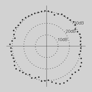
Illustration:
Read the noise value from the noise circle. Use the mean value of the readouts at 0 degrees (straight up).
Procedure
- Make sure that you have sufficient water depth below the keel before you lower the transducer.
- Lower the transducer to its bottom position.
- Select the default
settings.
- On the Main menu, select User Settings.
- Observe the Factory Settings list.
- Select the setting you want to use.
- Select Activate Selected Setting.
- Select OK to apply your changes and close the User Settings dialog box.
- At the bottom of the display presentation, select a suitable presentation mode, and activate the Horizontal view.
- Make the following
preparations.
- On the Main menu: Set Range to 1500 m.
- On the Operation menu: Set Tx Power to Off.
- On the Active menu:
- Set Pulse Type to CW Medium.
- Set Frequency to the start frequency: 14 kHz
- Set Vertical TX Sector to Narrow.
- Set Noise Filter to Off.
- Set the Bottom Filter Threshold to Off.
- On the Setup menu: Select Diagnostics to open the dialog box.
- Select Noise to open the page.
- Establish a separate communication line with the bridge to verify the vessel speed during the test.
- Measure the flow noise
versus the vessel speed.
- Ask the bridge to increase the vessel speed to the maximum permitted speed for the hull unit.
- Wait until maximum speed has been obtained.
- Ask the bridge to abruptly turn off all engine power and - if possible - change the pitch of the propellers to zero.
- Read the noise value from the noise circle.
- For every knot the speed is reduced, read the noise.
(If you find it more convenient, type the data directly into the spreadsheet.)
- Fill in the result table.
- When all the measurements have been made, type the data (speed and noise) into a spreadsheet to create the curve.
- Hoist the transducer back up to its upper position.
| Speed/Frequency/Noise | ||
|---|---|---|
| Speed | Frequency | Noise level |
| 20 | ||
| 19 | ||
| 18 | ||
| 17 | ||
| 16 | ||
| 15 | ||
| 14 | ||
| 13 | ||
| 12 | ||
| 11 | ||
| 10 | ||
| 9 | ||
| 8 | ||
| 7 | ||
| 6 | ||
| 5 | ||
| 4 | ||
| 3 | ||
| 2 | ||
| 1 | ||
| Sea state: | ||
| Water depth: | ||
| Use this table to record the values. Print it out and make multiple copies. Alternatively, you can type the values straight into a spreadsheet. | ||