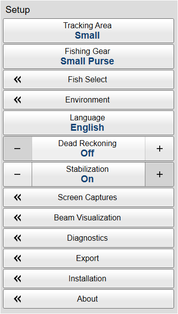
Setup menu

The Setup menu provides basic functions related to the installation parameters and the communication with peripheral systems.

How to open

Select the Setup icon.

The icon is located under the Main menu. Select the icon one more time to close the menu.

Description

Only brief descriptions are provided.

For detailed information about each function, page or dialog box, refer to the Functions and dialog boxes chapter in this publication.

Tip:

If you do not need to use the menu system, you can hide it. This allows more space for the echo presentation.

Use the Menu on the top bar to hide or show the menu. When the menu system is hidden, it appears temporarily on the left or right-hand side of the screen if you move the cursor to that position.

Context sensitivity

This is a highly adaptive menu. The choices in this menu depends on which view in the display presentation that is currently "active". The menu may therefore change from one view to another. The name of the currently active view is identified at the top of the menu. The screen capture may not show you all the menu choices.

Note:

Before you can change the settings related to a view, you must click inside the view to activate it. The changes you make are by default only valid for the active view. Several of the functions offer Apply to All. If you select Apply to All your setting is applied to all the views simultaneously.

Functions and dialog boxes

Tracking Area

Use the Tracking Area function to define the size of the area that you want to detect moving objects in. An invisible area - the tracking area - is created as an acquisition area. In order for the ST90 system to find and lock on the intended target, it needs to be kept within this tracking area. If the intended target falls outside the area, the tracking can not be started.

Fishing Gear

By defining the type of fishing gear you are using, the ST90 system may provide more accurate visual presentations. Use the Fishing Gear Setup dialog box to change the fishing gear properties to match your own equipment.

School Select

During normal operation, the detection and estimation of fish schools depends on the specie and the density of the school. The School Select function offers a selection of species. Based on your choice the ST90 system will adjust its operating parameters to achieve optimal performance.

Open the School Mass Adjustment page to adjust the density for a given specie, or to create you own school parameters.

Environment

Environmental parameters such as salinity, sound speed and water temperature all play an important part to present accurate echo data. Use the Environment parameters to define these values. Depending on the current sea and weather conditions, you may need to change these values frequently.

Language

You may prefer to use the ST90 system with the user interface in your own language. A selection of languages is provided. The Language function allows you to select the language to be used in the display presentations, menus and dialog boxes.

Dead Reckoning

The Dead Reckoning function is used to improve the position of the track line relative to the actual position of the drifting fishing gear. For this function to operate, the ST90 system requires input from a speed log.

Stabilization

The ST90 system is provided with a built-in motion sensor to provide electronic stabilization of the sonar beams. If the sensor is malfunctioning the input can be disabled.

Screen Captures

While using the ST90 system you may wish to make a screen capture to save an instantaneous copy of the current presentation. You can choose either a single screen capture or a sequence with multiple screen captures.

Beam Visualization

With the various beams provided by the ST90 system, it may be difficult to understand the concepts. How do these beams "behave" in the water? The beam visualization feature simulates how the acoustic beams cover the seabed and the water column.

Diagnostics

The ST90 system is a computerized sonar. There are hardly any analogue circuitry, and the possibility of traditional troubleshooting is limited. In order to rectify this, a built-in software application is available to offer test and maintenance functionality. The Diagnostics dialog box controls the test and diagnose application that checks the performance of the ST90 system.

This dialog box contains a number of pages selected from the menu on the left side.

The following pages are provided:

Processor

The Processor page offers an overview of the parameters related to software version, operation and network.

Sensors

The Sensors page presents a table with all the sensors currently connected to the ST90 system. For each sensor, the status is provided.

Transceiver

The Transceiver page offers key information about each transceiver board in the Transceiver Unit.

The purpose of the transceiver boards is to first create and transmit the acoustic pulses. After the transmission the transceiver boards receive the echoes from the seabed and/or the water column. These echoes are filtered, amplified and finally converted into digital format. This transmission and reception sequence is commonly referred to as a ping.

Transducer

Use the Transducer page to do a reception test to check the individual transducer elements. Any errors are then easily detected.

Noise

The operational performance of the ST90 system depends on the noise conditions. It is essential that the noise signature is as low as possible.

Export

The Export dialog box allows you to export user settings, configuration files, message logs and information mainly related to hardware and software troubleshooting.

Installation

Before you use the ST90 system you must set it up to communicate with the relevant peripherals. This includes the transducer. Use the Installation dialog box to set up all interfaces with external devices, and to set up basic parameters related to installation and operation. In most cases, you only need to do this once.

This dialog box contains a number of pages selected from the menu on the left side.

The following pages are provided:

Sensor Installation

For the ST90 system to use and offer correct navigational information, one or more external sensors must be connected. Typical sensors are those providing navigational information (heading, speed or geographical position). Use the Sensor Installation page to define which external sensors your ST90 system will import information from. You must also specify which datagram formats to use. For each relevant sensor you must insert the offset values that define the its physical location relative to the vessel’s coordinate system.

Sensor Configuration

With multiple sensors connected to the ST90 system, many of them will provide the same datagrams. We cannot expect that these datagrams provide the same information. The Sensor Configuration page allows you to define a datagram priority, so that the information from the "most reliable" sensor is used by the ST90 system. You can also define manual values in case a sensor is unserviceable, or not installed.

I/O Setup

To communicate with peripheral devices the Processor Unit offers several serial and/or Ethernet (LAN) ports. The number of communication ports depends on how your Processor Unit is set up and configured. The parameters on the I/O Setup page allow you to control the properties of each of the available communication ports. For each port, you can set up the communication parameters, and monitor the data flow.

Motion Reference Unit

The motion reference unit (MRU) measures the roll and pitch movements of the vessel. Some sensor models also measure heave. The information provided by the motion sensor is used by the ST90 system to stabilize the beams.

Installation Parameters

The Installation Parameters pages allow you to define the relationship between the physical locations of the various sensors and the transducer. All relevant system units and sensors must be defined with their physical offset values in relation to the defined Ship Origin in the vessel’s coordinate system. You will only need to define these installation parameters once.

Synchronization

The purpose of the Synchronization parameters is to set up the ST90 system to operate alone, or as a master or slave in a synchronized system. Synchronization is required in order to avoid interference if the ST90 system is used simultaneously with other hydroacoustic instruments within the same frequency range.

Units

The user interface presents many measurements. These measurements are for example related to depth, range and distance. From the Units page you control which units of measurements are used.

Operating Panel

The Operating Panel offers all necessary control functions for normal operation. It further allows you to assign certain functions to dedicated buttons and switches. The Operating Panel page is used to select which physical hardware panel you use, and to assign functionality to the programmable buttons.

Echogram Settings

The ST90 system offers several inspection beams. Each inspection beam is presented using an Inspection view. Use the Echogram Settings page to set up basic functionality for the Inspection views.

Hull Unit Configuration

The hull unit is used to lower the transducer down below the ship’s hull when the ST90 system shall be used. When the ST90 system is turned off, the transducer is hoisted for protection. Use Hull Unit Configuration to specify the type of hull unit your ST90 system is using.

System Protection

The System Protection parameters allow you to define your own warning limits for the ST90 system.

Fishing Gear

By defining the type of fishing gear you are using, the ST90 system may provide more accurate visual presentations.

Map Setup

If you want to add a map to the display presentation you must first select a map provider. Use the Map Setup page to choose a map provider and to enter necessary provider URL, API Key or license. In order to use this functionality, a dedicated software license is required. Contact you local dealer for more information.

User Settings Setup

The User Settings dialog box allows you to save the current user settings (your current selection of operational parameters), and to retrieve factory or previously saved user settings. These settings can be related to different operations, environmental conditions or basic personal preferences. By default, information about the current range, bearing and tilt will not be saved. On the User Settings Setup page, tick the box to include range, bearing and tilt information the next time you save the user settings.

Software License

The ST90 system does not need any software licenses to operate. However, specific software license codes "unlocks" additional functionality. The Software License settings allow you to type a license code (text string) to unlock these optional functions.

Transceiver Upgrade

The ST90 system offers a large number of transceiver channels. 12 identical transceiver boards are used. Certain functions offered by the ST90 system may require the firmware on these transceiver boards to be upgraded. For more information, refer to the relevant software release note.

Simrad Connect

The purpose of the Simrad Connect page is to make the ST90 system available for remote control with a suitable portable device.

About

Each software release for the ST90 system is uniquely identified. The About dialog box identifies the current software version with its release date. The version described in this publication is 24.7.X.

Tip:

For detailed information about each function and dialog box, refer to the Reference Manual or the context sensitive on-line help.