270 Vertical view
The 270 Vertical view is designed for purse seining. The presentation combines a horizontal "bow up" presentation with a vertical slice.
At the bottom of the display presentation, select a suitable presentation mode, and activate the 270 Vertical view.
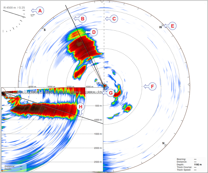
- The current settings for range, gain and tilt are shown in the upper left corner of the view.
- The current bearing is shown with a solid line pointing out from the vessel position.
- The bow marker is shown as a dotted line drawn from the bow of the vessel symbol.
- In the Horizontal view, the coverage plot identifies the area covered in the Vertical view.
- Activate Compass Cards to place evenly spaced compass markers on the outer range ring in horizontal views.
- Range rings are a set of concentric circles labelled by distance from the vessel position.
- A line of X’es in the vertical views shows the bottom of the purse seine. The depth is defined for the fishing gear you have chosen.
- You can change the tilt angle by means of the Tilt function on the Main menu. You can also click on the tilt line in a Vertical view and drag it up and down.
By default, the vertical view is shown in the lower left corner of the presentation. This position is used when you have the net on your starboard side. If you use a net on your port side, you can place the view in the bottom right corner.
By defining the type of fishing gear you are using, the ST90 system may provide more accurate visual presentations. Use the Fishing Gear Setup dialog box to change the fishing gear properties to match your own equipment.
Set throw side to Port or Starboard.
Under Fishing Gear, select Fishing Gear Setup to open the dialog box. This dialog box is also provided as a page in the Installation dialog box.
This view makes it easy to keep contact with the school. You can determine its size distribution, and monitor the position the school relative to the bottom.
Although the presentation of the echoes is most important in this view, it also contains a number of other objects. These provide you with additional functionality, as well as information that is useful or important while using the ST90 sonar system.
- Gain
The current settings for range, gain and tilt are shown in the upper left corner of the view. Click on the text to make it larger. Click one more time to restore the original font size.
The purpose of the Gain function is to adjust the echo level in the display presentations. By adjusting the gain you can control how much amplification the ST90 system applies to the received echoes.
- Bearing
The current bearing is shown with a solid line pointing out from the vessel position. You can change the angle by means of the Bearing function on the Main menu. You can also select the bearing line and drag it sideways.
The bearing for the Vertical view is controlled by the bearing in the Horizontal view.
Tip:The Bearing function controls the horizontal direction of the Vertical view, the audio beam and the beam in each Inspection view.
By default, a new manually initiated tracked object is automatically given priority status. The priority is identified with a "P". The bearing and tilt settings are automatically adjusted to follow the movements of the tracked target. The bearing line is automatically locked on the object to reflects its bearing.
- Range / Range Rings / Variable Range Ring
The distance from the vessel symbol in the centre of the circle to the outer ring corresponds to the currently selected range.
The current settings for range, gain and tilt are shown in the upper left corner of the view. Click on the text to make it larger. Click one more time to restore the original font size.
Range rings are a set of concentric circles labelled by distance from the vessel position. The selected range is divided into identical distances. The range rings are shown as dotted curves. Each ring has a range read-out. Use the Range Rings function to toggle the range rings On or Off.
Variable Range Ring adds an adjustable range ring to the view. The ring is shown as a dotted circle with its centre on the vessel symbol. The current range is shown next to the circle. To change the range, left-click on the circle and drag to requested diameter. You can use VRR Range to manually define a range. The variable range ring can be used for any type of distance measurement relative to the sonar.
- Tilt
The current settings for range, gain and tilt are shown in the upper left corner of the view. Click on the text to make it larger. Click one more time to restore the original font size.
When you change the tilt a dotted line presents the requested tilt while the solid line presents the actual tilt. You can change the tilt angle by means of the Tilt function on the Main menu. You can also click on the tilt line in a Vertical view and drag it up and down. If you place the cursor over the tilt presentation in the upper left corner of the Horizontal view you can use the scroll wheel to change the tilt.
- Bow Marker
The bow marker is shown as a dotted line drawn from the bow of the vessel symbol. The line reflects your vessel’s current heading. The bow marker can be enabled or disabled on the Visual Objects menu.
- Cursor
The distance and depth of the cursor location is shown in the lower right (or left) corner of the view. The depth is calculated from the current tilt and the distance from the vessel. If you place the cursor over the tilt presentation in the upper left corner of the Horizontal view you can use the scroll wheel to change the tilt.
- Compass Cards
Activate Compass Cards to place evenly spaced compass markers on the outer range ring in horizontal views. The compass markers rotate based in the inputs from a navigation sensor. An update takes place when the vessel heading changes more than 1 degree.
- Coverage Plot
When you operate with sector transmissions, the area covered by the sonar beams is limited by the chosen transmit sector angle. To make it easier to recognize the area limits, dedicated border lines may be added to the presentation. These lines are used to outline the sector.
In the Horizontal view, the coverage plot identifies the area covered in the Vertical view.
- Current Vectors / Current Flow
A current sensor can be connected to the ST90 system. This can for example be an acoustic Doppler current profiler (ADCP). The information from this sensor is presented in the applicable views.
The Current Vector function shows you the speed and direction of the water current under your vessel. One or more arrow are drawn to or from the vessel symbol to indicate the properties of the sea currents. The direction of the arrows indicate the direction of the water currents. The length of the arrows reflects their speeds. A numerical readout of the current vector data is provided in the top right corner of the Horizontal view.
The Current Vector function is located on the Visual Objects menu. Use the Current Flow page to define key settings for the presentation of the sensor data. This page is located in the Display Options dialog box.
- Minute Markers
In order to maintain a visual presentation of your vessel’s previous movements, you can draw these with a line. This line is drawn after the vessel symbol in the sonar views, and visualizes your past movements. We refer to this line as the Track Line. The Minute Markers function adds markers to the track line. These markers indicate how far you have sailed in the last few minutes. The minute markers are shown as small circles on the vessel’s track line.
Tip:To draw the track line use the settings on the Track Line page. The Track Line page is located in the Display Options dialog box. The Display Options dialog box is located on the Display menu.
- Purse seine
A line of X’es in the vertical views shows the bottom of the purse seine. The depth is defined for the fishing gear you have chosen. The depth is calculated from the sink rate you have defined for the fishing gear. Use Purse Depth on the Cosmetics menu to toggle this line On or Off.
Tip:Under Fishing Gear, select Fishing Gear Setup to open the dialog box. For the selected purse, set the sink rate. For the selected purse, select a depth value.
If you have connected a compatible catch monitoring system to your ST90 system, information from these sensors are shown in the Catch view.
The Cosmetics menu controls which "cosmetic" features that used.
Before you can change the settings related to a view, the view must be active. To activate a view, click in it. The active view is identified with a thicker border.