Inserting the installation parameters for the transducer
When the installation trunk is mounted, it may not be positioned with the mounting holes perfectly aligned to the centre line of the vessel. When the hull unit is placed on the trunk, the "forward" mark on the transducer shaft sleeve - and thus also "forward" on the transducer - may not point forward at all, but several degrees off the centre line. To obtain accurate echo presentations, this misalignment must be adjusted by changing the installation parameters. Providing the correct value for this rotation is crucial for the sonar performance. An inaccurate or incorrect value will cause the sonar echoes to be presented at the wrong bearing.
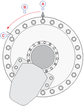
Illustration:
- Bow
- This is the alignment angle (±180°)
- 0° transducer mark
The ST90 system has been set up with its hardware units connected as specified in the Installation Manual.
- The ST90 system is turned on.
- The ST90 system does not transmit ("ping").
- The transducer is retracted to its upper position.
- The vessel is berthed or at sea.
You must never set the ST90 system to ping unless the transducer is submerged in water. The transducer can be damaged if it transmits in the open air.
For accurate location of the transducer, you need the detailed vessel drawings. You also need the installation angles that were recorded when the transducer was installed.
As a general recommendation, the hull unit shall be oriented with the hoisting motor pointing aft. If this orientation makes it difficult to access electrical connections, the hull unit may be rotated during its installation to the most suitable direction. Independent of the hull unit orientation, the alignment is always defined as:
The angle measured from the bow to the 0° transducer mark.
The 0° transducer mark is located outermost on the mounting flange, and it is marked as a red "0". Depending on the transducer mounting, it can be located at any angle on the mounting flange, not necessarily as shown in the illustration.
On the Transducer page, define this angle as rotation around Z.
- If the 0° transducer mark points to the starboard (right) side of the vessel’s centre line, insert the alignment as a number between 0 and +180 degrees.
- If the 0° transducer mark points to the port (left) side of the vessel’s centre line (as shown in the illustration), insert the alignment as a number between 0 and –180 degrees.
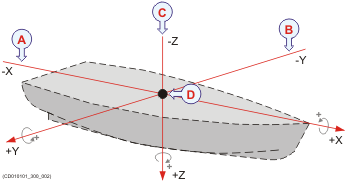
Illustration:
- Rotation around the x-axis: In the positive horizontal direction (forward), a positive rotation is clockwise.
- Rotation around the y-axis: In the positive horizontal direction (starboard), a positive rotation is clockwise.
- Rotation around the z-axis: In the positive vertical direction (down), a positive rotation is clockwise.
- Reference point (Ship Origin)
Procedure
- Open the Setup menu.
- On the Setup menu,
select Installation.

Observe that the Installation dialog box opens. This dialog box contains a number of pages selected from the menu on the left side.
- On the left side of
the Installation dialog box, select the small white triangle next to Installation Parameters.
Observe that a menu opens with access to all the individual pages.
- Select Transducer to open the page.
- Insert
the relevant offset values.
Do this as accurately as possible.
- X Offset: Insert the horizontal distance on the x-axis (fore-and-aft direction) between the transducer and the Ship Origin.
- Y Offset: Insert the horizontal distance on the y-axis (athwartship direction) between the transducer and the Ship Origin.
- Z Offset: Insert the vertical distance on the Z axis between the transducer and the Ship Origin.
- Obtain the rotation (angle) information from the personnel
that installed the hull unit.
Insert the values. Do this as accurately as possible.
- Rotation Around X: Specify an angle (in degrees) to compensate for any deviation from the X axis (fore-and-aft direction) in the vessel coordinate system. If the transducer is properly installed without unintentional skew, this angle can be set to 0 degrees.
- Rotation Around Y: Specify an angle (in degrees) to compensate for any deviation from the Y axis (athwartship direction) in the vessel coordinate system. If the transducer is properly installed without unintentional skew, this angle can be set to 0 degrees.
- Rotation Around Z: Specify an angle (in degrees) to compensate for any deviation from the Z axis (vertical direction) in the vessel coordinate system. This is the alignment angle.
- If the 0° transducer mark points to the starboard (right) side of the vessel’s centre line, insert the alignment as a number between 0 and +180 degrees.
- If the 0° transducer mark points to the port (left) side of the vessel’s centre line (as shown in the illustration), insert the alignment as a number between 0 and –180 degrees.
Examples:
- If the alignment angle is 295 degrees, insert -65 degrees.
- If the alignment angle is 15 degrees, insert 15 degrees.
- At the bottom of the page, select Apply to save your settings.
- Continue your work in the Installation dialog box, or select OK to close it.