Fish Position page
The Fish Position information pane shows the position of the detected single fish echoes. The information pane is only available when an Inspection view is "active". Use the Fish Position page to set up the presentation parameters for the Fish Position information pane.
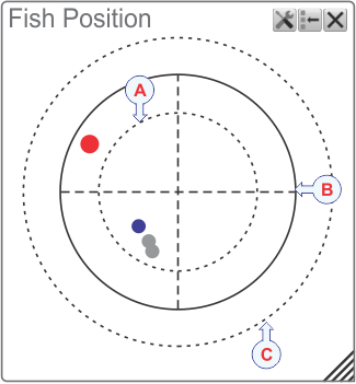
The dotted inner circle identifies the low frequency in the sweep.
The circle between them identifies the centre frequency.
The outer dotted circle identifies the high frequency.
How to open
This page can be opened from several places in the user interface. The page is opened in the Information Pane Options dialog box. You can also select the Setup button in the relevant information pane.

The Information Pane Options dialog box is only available when an Inspection view is active.
Description
Each coloured circle in the information pane identifies a single fish. You can observe how these move through the beam. The colours used are the same as the colours used in the colour scale, and these indicate the echo strength from each fish. This information pane can be useful during trawling. Keep an eye on the Fish Position information pane to make sure that you can manoeuvre the trawl through the areas with most fish.
Several specific parameters are available for studies of single fish. In order to detect single fish correctly, these parameters should be defined to suit the specie characteristics.
Details
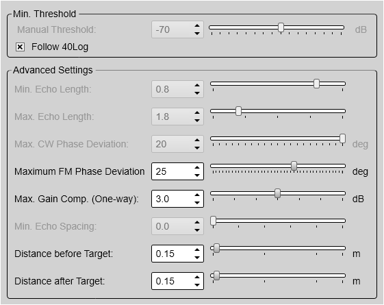
- Minimum Threshold
Some echoes are stronger than others. If you have noise problems, or you are bothered with for example smaller fish (different species), jellyfish or plankton, you can use the Minimum Threshold function to adjust the sensitivity. The target strength (TS) for a single target must exceed this threshold (in dB) to be accepted.
Use this function to define a "filter" value.
- Follow 40 Log
Select this option to let the threshold follow the minimum level defined on the Colour Scale page for the corresponding channel.
- Minimum Echo Length / Maximum Echo Length
These settings only apply to CW operation.
The echo from a single target will normally have a similar (or slightly longer) length than the length of the transmitted signal. This is due to the physical properties of the target.
- Maximum CW Phase Deviation
This setting only applies to CW operation.
Several single targets occurring at the same range will give you echoes in different parts of the beam’s cross section. All samples in an echo from a single target will normally have similar phase value (angles) as the samples arrives from the same location. Echoes from multiple targets or random noise will show great variation in phase.
To remove the bad targets, the angle (phase) between the samples in the echo are measured. If the angle is too large, the echoes are deleted.
- Maximum FM Phase Deviation
This setting only applies to FM operation.
Several single targets occurring at the same range will give you echoes in different parts of the beam’s cross section. To remove the bad targets, the angle (phase) between the samples in the echo are measured. If the angle is too large, the echoes are deleted.
If the angle at a given range is too large, this indicates multiple targets.
- Maximum Gain Compensation
This setting applies to both CW and FM operation.
Not all single targets are located in the centre of the beam. Targets located off centre will offer weaker echoes due to the beam properties. The ST90 system automatically compensates for this using a mathematical model, and you can manually control the effect of this algorithm by defining a maximum gain value.
- Minimum Echo Spacing
This setting only applies to CW operation.
This parameter defines the minimum distance between two single echoes when you are using CW pulses. If they are too close, the echoes are skipped.
- Distance Before Target / Distance After Target
These settings only apply to FM operation.
The Distance Before Target and Distance After Target settings define the required spacing before and after one target to the end and beginning of the next target. This is the same functionality as the Minimum Echo Spacing function for CW operations, but the algorithms are very different.
They also define the range of target samples which are used for Fourier transformation to create the target strength frequency response (the curve in the TS(f) information pane) and the target position phase values.
Increasing the distance values will require the targets to be further separated, but can increase the frequency resolution for the target strength frequency response (in the TS(f) information pane).
The value for the Distance After Target should normally be larger than the value for Distance Before Target due to the backscattering properties of a target. The values are specified in meters and are applied on the matched filtered/pulse compressed sample data.