Vertical view
The Vertical view is oriented perpendicularly to the horizontal plane. The Vertical view shows you a "vertical slice" of the echo data. The direction of the vertical slice is indicated and controlled by the bearing line in the Horizontal view. The area covered by the vertical beam is shown as a triangle in the Horizontal view. The upper horizontal line in the view represents the water surface.
To activate the Vertical view, select a suitable presentation mode on the bottom bar, then click inside the view.
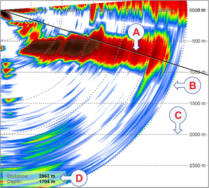
- The current tilt is shown with a solid line.
- The range rings are shown as dotted curves.
- Horizontal dotted lines show the depth intervals.
- The distance and depth of the cursor location is shown in the lower left corner of the view.
Description
By default, the vertical views have the transducer located in the upper left corner of the view. The presentation is made from left towards right.
The Vertical View Orientation page allows you to decide whether the vertical views should be presented from right to left, or from left to right. This page is located in the Display Options dialog box. This dialog box is opened from the Display menu.
Certain presentation modes provide more than one vertical view. You can then set up these views individually.
To fully understand how the beams behave in this view, use the Beam Visualization dialog box. This dialog box is opened from the Setup menu.

The Cosmetics menu controls which "cosmetic" features that used.

The Visual Objects menu controls which graphical elements that are shown in the different views.

Before you can change the settings related to a view, the view must be active. To activate a view, click in it. The active view is identified with a thicker border.
Although the presentation of the echoes is most important in this view, it also contains a number of other objects. These provide you with additional functionality, as well as information that is useful or important while using the ST90 sonar system.