Bearing function
The Horizontal view presents the 360 degrees area around your vessel from a bird’s eye view. For the other views you must define the horizontal direction of the beam. Use Bearing to adjust the horizontal angle referenced to the vessel heading. You can also select the bearing line and drag it sideways.
How to open
This function is opened from the Main menu.
Description
The Bearing function controls the horizontal direction of the Vertical view, the audio beam and the beam in each Inspection view. The current bearing applied to the Horizontal view is shown with a solid line pointing out from the sonar position.
- The bearing for the Vertical view is controlled by the bearing in the Horizontal view.
- If you use a presentation mode with two horizontal views you can set Bearing to two different values. Both bearing lines are shown in the Horizontal view. Both bearings are shown as continuous lines pointing out from the sonar position. The bearing in Horizontal 1 is shown with a solid line. The bearing in Horizontal 2 is shown with a dotted line.
- If you use a presentation mode with two vertical views you can set the Bearing function to two different values. Both bearing lines are shown in the Horizontal view. The bearing for the Vertical view is shown with a solid line. The bearing for the Vertical 2 view is shown with a dotted line.
- The solid bearing line in the Horizontal view controls the audio beam. If you have two Horizontal views, the solid line in the Horizontal 1 view controls the audio beam.
- The area covered by the vertical beam is shown as a triangle in the Horizontal view.
The choice you make is by default only applied to the currently selected (active) view. The active view is identified with a thicker border.
By default, a new manually initiated tracked object is automatically given priority status. The priority is identified with a "P". The bearing and tilt settings are automatically adjusted to follow the movements of the tracked target. The bearing line is automatically locked on the object to reflects its bearing.
Details
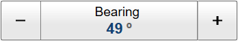
- Bearing
The following methods can be used to adjust this setting:
- In a Horizontal view, select the bearing line and drag it sideways.
- Use the Operating Panel.
- Select either side of the button to choose a value.
- Select the middle of the button to open it. If you have a keyboard connected to the ST90 system, type the requested value.
- Auto
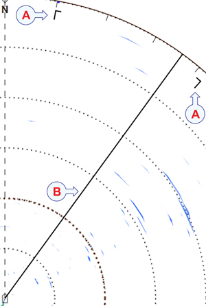
This is an "on/off" function. Set this function to On to start the automatic search function. In the Auto Bearing mode the ST90 system will automatically search within defined sector limits. The sector is identified in the view using two angular symbols.
Illustration:
- Search sector
- Bearing line
- Step
Select Step to set the size of each tilt step (in degrees) in Auto Bearing mode.
Select either side of the button to choose a value. Select the middle of the button to open it. If you have a keyboard connected to the ST90 system, type the requested value.
- Sector
Select Sector to set the size (in degrees) of the horizontal search sector in Auto Bearing mode.
Select either side of the button to choose a value. Select the middle of the button to open it. If you have a keyboard connected to the ST90 system, type the requested value.
Related functionality
- Operating Panel
The Mk1 Operating Panel offers separate Train buttons to control of the horizontal angle of the sonar beams as referenced to the vessel heading. (The Mk1 Operating Panel is no longer provided with new sonars. This information is provided for legacy reasons.)
The Mk2 Operating Panel is fitted with three rotary switches. The Mk3 Operating Panel is fitted with two rotary switches. The switches are identified with numbers. Each switch can be assigned a function related to range, gain, bearing or tilt. The Operating Panel page is used to assign functionality to the programmable buttons. This page is located in the Installation dialog box.
- Microsoft Xbox Controller
This function can also be controlled from a Microsoft Xbox Controller connected to the Processor Unit.