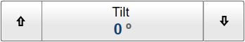
Tilt function
The Tilt function allows you to control the vertical angle of the sonar beams.
Specifications: Tilt
- Horizontal views: –10 – 60 degrees
- Vertical views: 0 – 90 degrees
- Plane view: –10 – 90 degrees
- Inspection views: –10 – 60 degrees
How to open
Open this function from the Main menu.
Description
The transmitted sonar beams can be tilted electronically. The following methods can be used to adjust this setting:
- Select either side of the button to choose a value.
- Select the middle of the button and keep the mouse button pressed. Drag the cursor sideways to increase or decrease the value. Release the mouse button when requested value is shown.
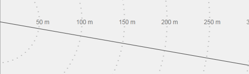
- In a Vertical view, click on the tilt line, keep the mouse button depressed, and drag the line up or down.
The current tilt is shown with a solid line in the Vertical views.
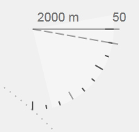
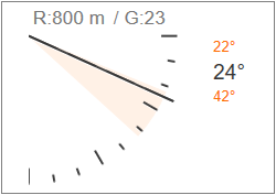
In the Horizontal views, the current settings for range, gain and tilt are shown in the top left corner of the view. When you change the tilt a dotted line presents the requested tilt while the solid line presents the actual tilt.
The tilt setting is only valid for currently selected (active) view. The tilt limits depend on the opening angle of the vertical beam. This means that you may not always be permitted to select the maximum specified tilt limits.
With the various beams provided by the ST90 system, it may be difficult to understand the concepts. How do these beams "behave" in the water? By means of a graphic presentation, the Beam Visualization dialog box attempts to give you a better understanding of how the acoustic beams are transmitted into the water. Open the Beam Visualization dialog box from the Setup menu.
Details
- Tilt
The following methods can be used to adjust this setting:
- Select either side of the button to choose a value.
- Select the middle of the button and keep the mouse button pressed. Drag the cursor sideways to increase or decrease the value. Release the mouse button when requested value is shown.
- Select the middle of the button to open it. If you have a keyboard connected to the ST90 system, type the requested value.
- Auto
This is an "on/off" function. When Auto Tilt mode is activated the beam will automatically change its tilt angle for each transmission ("ping").
The centre of the tilt sector is defined by the chosen tilt angle just before the Auto Tilt mode is started. The chosen tilt sector is shown on the tilt indicator in the Horizontal view using a shaded background.
Select Step to set the size (in degrees) of each tilt step.
Select Sector to set the size (in degrees) of the vertical tilt sector.
Tip:The Mk2 Operating Panel is fitted with three function buttons. The buttons are identified as F1, F2 and F3. One of these buttons can be assigned to activate the Auto Tilt mode. The Operating Panel page is used to select which physical hardware panel you use, and to assign functionality to the programmable buttons. This page is located in the Installation dialog box.
- Step
Select Step to set the size of each tilt step (in degrees) in Auto Tilt mode.
Select either side of the button to choose a value. Select the middle of the button to open it. If you have a keyboard connected to the ST90 system, type the requested value.
- Sector
Select Sector to set the size (in degrees) of the vertical tilt sector in Auto Tilt mode.
Select either side of the button to choose a value. Select the middle of the button to open it. If you have a keyboard connected to the ST90 system, type the requested value.
- Link Inspection Beams
This is an "on/off" switch. Activate Link Inspection Beams to "connect" all the inspection beams together. Select Apply to All use the chosen setting in all the Inspection views. When the beams are linked, they are tilted simultaneously. The distance between each beam is fixed, and defined by the value you have chosen for Beam Spacing.
You can link the inspection beams for both vertical and horizontal movements. You can not link both tilt and bearing at the same time.
- Beam Spacing
Select a value for Beam Spacing to define the distance (in degrees) between the linked beams.
- Link Horizontal Pings
This is an "on/off" switch. Activate Link Horizontal Pings to "connect" all the horizontal transmissions to each other. Select Apply to All if you want to use the chosen setting in all the horizontal views. When the beams are linked, they tilt together but do not necessarily use the same angle. The distance between each beam is fixed, and defined by the value you have chosen for Beam Spacing.
- Beam Spacing
Select a value for Beam Spacing to define the distance (in degrees) between the linked beams.
- Apply to All
Check this box if you wish to use the chosen setting in all the Inspection views.
Related functionality
- Operating Panel
The Mk1 Operating Panel offers separate Tilt buttons to control the vertical angle of the sonar beams.. (The Mk1 Operating Panel is no longer provided with new sonars. This information is provided for legacy reasons.)
The Mk2 Operating Panel is fitted with three rotary switches. The Mk3 Operating Panel is fitted with two rotary switches. The switches are identified with numbers. Each switch can be assigned a function related to range, gain, bearing or tilt. The Operating Panel page is used to assign functionality to the programmable buttons. This page is located in the Installation dialog box.
- Microsoft Xbox Controller
This function can also be controlled from a Microsoft Xbox Controller connected to the Processor Unit.