Sensor Installation page
For the ST90 system to use and offer correct navigational information, one or more external sensors must be connected. Typical sensors are those providing navigational information (heading, speed or geographical position). Use the Sensor Installation page to define which external sensors your ST90 system will import information from. You must also specify which datagram formats to use. For each relevant sensor you must insert the offset values that define the its physical location relative to the vessel’s coordinate system.
How to open
This page is located in the Installation dialog box. To open the page, select Installation on the Setup menu.
Prerequisites
The Installation dialog box is not available when your ST90 system is set to Replay mode.
Description
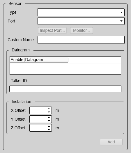
The Sensor Installation page allows your ST90 system to communicate with external sensors and systems. The parameters are organized in groups.
- Installed Sensors
The Installed Sensors list contains all the sensors that are currently installed on the ST90 system. Select a sensor in the list to edit its interface properties, or to remove it. Select New in the list to add a new sensor interface to the ST90 system.
- Sensor
In the Sensor group you select which type of sensor you want to receive information from. You must specify which communication port to use (LAN (Local Area Network) or serial port). You can type a custom name to identify the sensor import. Select Inspect Port to verify that the communication parameters of the chosen port have been set up correctly.
- Datagram
In the list of valid datagram formats, select the format(s) to be accepted by the ST90 system. If necessary, you can also specify a specific Talker ID.
- Installation
Most sensors are physically mounted somewhere on your vessel. For accurate measurements, the sensor locations - referenced to the vessel’s coordinate system - must be known to the ST90 system.
Just making changes and selecting OK at the bottom of the page will not install anything. Select what to install, define the relevant parameters, and then select Add.
A summary of all the sensors that are connected to the ST90 system is provided in the Diagnostics dialog box.
Details
- Installed Sensors
The Installed Sensors list contains all the sensors that are currently installed on the ST90 system. Select a sensor in the list to edit its interface properties, or to remove it. Select New in the list to add a new sensor interface to the ST90 system.
- Type
The ST90 system can communicate with several different sensor types. Under Type, select which type of sensor you want to receive information from.
- Port
To import the data from the chosen sensor you need to define an input port. This can be any available Local Area Network (LAN) or serial line on your Processor Unit.
We recommend that you set up the relevant communication parameters before you use the port. To set up the communication parameters, use the I/O Setup page. The I/O Setup page is located in the Installation and Output dialog boxes.
- Inspect Port
Select Inspect Port to check the communication parameters for the port. The relevant port setup dialog box opens.
- Monitor
This option is only available if you decided to edit the parameters of a previously installed sensor. Select Monitor to open the Port Monitor dialog box. The Port Monitor dialog box allows you to study the communication stream on the chosen serial line or local area network (LAN) port.
- Custom Name
For easier recognition of the sensor interface, you can type a custom name. This name is shown in other dialog boxes in the user interface. If you do not have a computer keyboard connected to your ST90 system, select the Keyboard button to open an on-screen keyboard.
- Datagram
The list presents the available datagram formats for the chosen sensor type. Select the datagrams you want to import.
- Talker ID
If you want to specify a dedicated Talker ID for the datagram format, it can be defined here.
- Offsets
The physical location of each sensor must be defined with reference to the vessel’s coordinate system.
- Rotation
For some sensors - typically motion sensors and transducers – the physical location of the sensor is not sufficient to extract accurate data. These sensors are installed with physical angles. These angles are often referred to as "installation angles" or "offset angles". The sensor can be rotated around the three axis of the vessel coordinate system.
- Add
When you have set the parameters for a new sensor interface, select Add to save it. Once a sensor has been added to the ST90 system configuration, it appears in the Installed Sensors list.
- Remove
The Installed Sensors list contains all the sensors that are currently installed on the ST90 system. If you want to delete a sensor, select it in the list, and then select Remove at the bottom of the Sensor Installation page.
Note:You cannot undo this operation.
- Edit
The Installed Sensors list contains all the sensors that are currently installed on the ST90 system. If you want to edit the parameters of a previously installed sensor, select it in the list, and then select Edit at the bottom of the Sensor Installation page.