Transceiver page
The Transceiver page offers key information about each transceiver board in the Transceiver Unit.
The purpose of the transceiver boards is to first create and transmit the acoustic pulses. After the transmission the transceiver boards receive the echoes from the seabed and/or the water column. These echoes are filtered, amplified and finally converted into digital format. This transmission and reception sequence is commonly referred to as a ping.
How to open
This page is located in the Diagnostics dialog box.

Open the Diagnostics dialog box from the Setup menu.
Description
The Transceiver page provides a graphic presentation of the transceiver boards. The visual presentation reflects the physical location of the boards in the Transceiver Unit. Only static information is provided. The Board Information parameters offer key information about the supply power to the selected transceiver board, as well as the environmental conditions.
The Diagnostics dialog box and functionality is only provided for performance monitoring. The functionality offered by the dialog box is not required for normal use of the ST90 system. The dialog box does not permit you to change any operational settings.
Details
- Boards
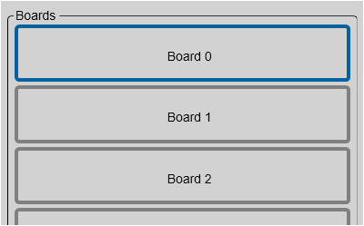
A graphic presentation of the transceiver boards is provided. The visual presentation reflects the physical location of the boards in the Transceiver Unit.
To select a transceiver board, click the "button". Relevant information about the selected transceiver board is provided under Board Information.
To disable or enable a transceiver board, right-click the "button" and use the short-cut menu.
- Board Information
The Board Information parameters offer key information about the supply power to the selected transceiver board, as well as the environmental conditions.
The text field contains software versions and other information related to the firmware on the board. This information is not useful for normal operation, but may be useful in a troubleshooting situation.
- Power Status
The Power Status parameters present information about the common supply voltages to all the transceiver boards in the Transceiver Unit. It also shows you the current position of the service switch on the power supply module.