Transducer page
Use the Transducer page to do a reception test to check the individual transducer elements. Any errors are then easily detected.
How to open
This page is located in the Diagnostics dialog box.

Open the Diagnostics dialog box from the Setup menu.
Description
The Transducer page presents all the elements that are used in the transducer. The presentation attempts to organize the elements in the same manner as in the physical transducer.
The transceiver boards are shown as "buttons". Select a transceiver board to highlight the elements that are physically connected to the board.
Details
- Boards
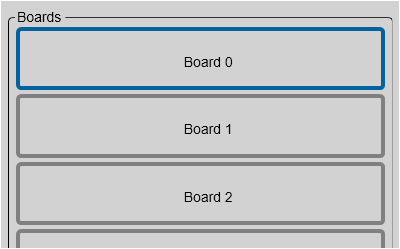
A graphic presentation of the transceiver boards is provided. The visual presentation reflects the physical location of the boards in the Transceiver Unit.
To select a transceiver board, click the "button". The corresponding transducer elements are identified.
- Transducer Elements
Each of the individual elements in the transducer is shown in a grid. The presentation attempts to organize the elements in the same manner as in the physical transducer.
Individual transducer elements may be disabled or enabled. To do this, right-click on the corresponding rectangle, and use the short-cut menu. A disabled element is shown with a blue rectangle.
Disabling a single transducer element can be useful for a number of reasons.
- An element is weak or simply unserviceable.
- An element is creating a lot of noise.
- Reception Test
Select Reception Test to start an automatic test of the individual transducer elements. For the reception test to start, the ST90 system must be transmitting (pinging). The reception test validates each element in the transducer.The test returns the results using colour codes.
- Green: The transducer element is fully operational.
- Red: The transducer element offers reduced performance.
- Black: The transducer element is not working ("dead").
For more information, observe the tooltip provided for each element rectangle.