Markers / Manual Track / Priority Marker
One or more markers can be placed in the view to identify specific echoes. Markers are shown as small triangles. Once an echo has been provided with a marker in the display presentation it is regarded as an object.
Each marker is numbered sequentially. Use Markers to control the presentation of the marker symbols in the currently active view. This function is located on the Visual Objects menu. Visual Objects is located on the Display menu.
The marker is stationary. It has a specified range, bearing and depth related to your own vessel. If the echo moves in the display presentation the marker will not follow.
The ST90 system automatically copies markers generated in the Horizontal view to the Vertical view and vice versa.
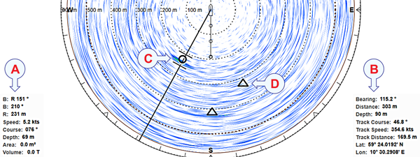
- Tracked target information / Priority marker information
- Cursor information / Manual track information
- The tracked target is regarded as an object, and it is identified with a circle and two lines. The two lines reflect the size of the current tracking area.
- Marker
When target tracking is activated, bearing and tilt are automatically adjusted to follow the movements of the tracked target.
You can give priority status to one marker to identify the relevant object as the most important target or position. Bearing and tilt are automatically adjusted to focus on the priority marker.
You can start manual tracking by placing multiple markers on a target echo that moves in the view. You can see the latest marker's course and speed in the view's lower right corner. The values are calculated based on the last two markers you created and the time between them. The physical location of the individual markers and the specific information provided for the latest marker show you the historical path of the chosen target. To read this information in the view's bottom right corner, you must enable it on the Cursor Readout page. This page is located in the Display Options dialog box.
Relevant information about a priority target can be found in the lower left corner of the view. The information includes the location, speed, course and depth of the target, as well as an estimate of its area and volume. To read this information in the view's bottom left corner, you must enable it on the Cursor Readout page. This page is located in the Display Options dialog box.
The Visual Objects menu controls which graphical elements that are shown in the different views. These graphic elements include markers, vectors and targets that are tracked. The majority of the functions are "on/off" buttons to enable or disable these graphic elements in the various views.