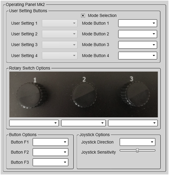
Operating Panel Mk2
The Mk2 Operating Panel is connected to the Processor Unit using an Ethernet cable. The Operating Panel is provided with a built-in power supply.
Details
- User Settings / Presentation Modes

On the Mk2 Operating Panel, the four buttons dedicated for user settings or presentation modes are located the top of the panel. Select Mode Selection to specify what you want to use the buttons for. Assign one predefined user setting or presentation mode to each button on the Operating Panel.
Tip:Before you can assign custom user settings to the operating panel, a selection of settings must be available from the User Settings dialog box. The User Settings dialog box is located on the Main menu.
Any user setting selected on the Operating Panel is identified in the upper left corner of the Horizontal view. The identifying number refers to the User Setting number on the Operating Panel page. Click on the text to make it larger. Click one more time to restore the original font size.
- Rotary Switch Options
The Mk2 Operating Panel is fitted with three rotary switches. The switches are identified with numbers. Each switch can be assigned a function related to range, gain, bearing or tilt.
Under Rotary Switch Options, assign one function to each rotary switch on the Operating Panel. The following functions can be assigned:
- Horizontal Range
This is the range setting in the Horizontal view.
- Horizontal Range 2
This is the range setting in the second Horizontal view when a "dual" presentation mode is used.
- Vertical Range
This is the range setting in the Vertical view.
- Vertical Range 2
This is the range setting in the second Vertical view when a "dual" presentation mode is used.
- Inspection Range
This is the range setting in the Inspection view.
- Plane Range
This is the range setting in the Plane view.
- Active Ping Range
This is the range setting in the currently active view.
- Active Ping Gain
This is the gain setting in the currently active view
- Active Ping Bearing
This is the bearing setting in the currently active view.
- Active Ping Tilt
This is the tilt setting in the currently active view
- Display Gain
Use this setting together with Gain to adjust the sensitivity of the ST90 system. Display Gain controls the "amount" of echo that is displayed, in other words the "strength" or "intensity" of the echo presentation. The function thus increases or decreases the presentation of the echo colours.
The gain is increased and decreased in steps of 1 dB. The chosen display gain will automatically apply to all the beams.
You can also control this functionality from the Display menu.
- Button Options
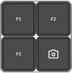
The Mk2 Operating Panel is fitted with three function buttons. The buttons are identified as F1, F2 and F3. Each button can be assigned a dedicated function. The three function buttons are grouped with the Screen Capture button.
Under Button Options, assign one function to each Fx button on the Operating Panel. The following functions can be assigned:
- None
No specific functionality is assigned.
- Auto Tilt
This is an "on/off" function. When Auto Tilt mode is activated the beam will automatically change its tilt angle for each transmission ("ping"). The centre of the tilt sector is defined by the chosen tilt angle just before the Auto Tilt mode is started. The chosen tilt sector is shown on the tilt indicator in the Horizontal view using a shaded background. The sector and step settings are made using the Tilt function on the Main menu.
- Zoom
Place the cursor anywhere in the view, right-click and select Zoom. Only one zoom level is provided. Select Zoom one more time to restore the original view.
- Menu Off
This is an "on/off" function. Unless you need to make frequent changes to the operating parameters, you may want to hide the menu from the display presentation. This gives you more space for echo information.
- Audio
Select Audio to turn the audio output on or off.
- Own Ship
This is the same function as Place Own Ship Marker on the shortcut menu. Select this function to add a square symbol to the vessel’s current position in the echo presentation. The own ship marker is now regarded as an object. All information about the object is shown in the Objects menu listed as "OSM". Use Delete Own Ship Marker on the shortcut menu to delete the marker from the current view.
- Auto Bearing
This is an "on/off" function. Set this function to On to start the automatic search function. In the Auto Bearing mode the ST90 system will automatically search within defined sector limits. The sector is identified in the view using two angular symbols. The sector and step settings are made using the Bearing function on the Main menu.
- Screen Recording
This is an "on/off" function. The Screen Recording function allows you to record and save the echo presentation as a video file. Each screen recording you make is saved in .mp4 format on the Processor Unit hard disk. The file name reflects the current date and time.
Select Screen Recording to start and stop the recording from the Operating Panel.
Use the Screen Recording page to define where the video files are saved. This page is located in the Output dialog box.
- Delete Oldest Marker
The ST90 system offers several different marker types. You can add as many markers as you like. The most common markers can be added using dedicated buttons on the Operating Panel. Other markers are added using the shortcut menu in each view. Each marker is identified with its geographical location.
Select Delete Oldest Marker to use the Operating Panel to remove the oldest marker from the echo presentation.
- Send to External
Each marker is identified with its geographical location. This marker location can be very useful for other instruments. For example, you can export this information to a chart plotter. You can configure your ST90 system to export marker information. You must choose a suitable output port and select which datagram formats to export.
Tip:Use the Output Marker page to export target markers to a communication port. This page is located in the Output dialog box. To open, select it on the Operation menu.
Place the cursor on the marker from which you want to export the target information. Press Send To External.
- Place Marker
Press Place Marker to create a visual marker symbol at the cursor's current position. Each marker is shown as a small triangle with or without a short identifying label.
In this context, the phrase marker is used to identify a visual symbol placed in the display presentation. A marker is thus a graphical indicator used to identify and highlight specific locations or objects. You can use markers to pinpoint and label interesting positions, objects or targets the ST90 system detects. Placing a marker on an echo identifies the echo as "interesting". It is regarded as an object that you can act upon.
- Delete All Objects
Placing a marker on an echo identifies the echo as "interesting". It is regarded as an object that you can act upon. You can add as many markers as you like.
Markers are shown as small triangles. Select Delete All Objects to remove all the markers from the views.
Tip:You can delete a single marker, or multiple markers simultaneously, by selecting Delete in the Objects menu. You can also use the shortcut menu to delete markers. If you use Delete Marker on the shortcut menu you can only remove one marker at a time.
- Increase Display Gain / Decrease Display Gain
Use Display Gain to increase or decrease the "strength" of the echo presentation.
Use this setting together with Gain to adjust the sensitivity of the ST90 system. Display Gain controls the "amount" of echo that is displayed, in other words the "strength" or "intensity" of the echo presentation. The function thus increases or decreases the presentation of the echo colours.
Adjust the Display Gain so that you can see the targets without too much noise and reverberation. The chosen setting is a matter of personal preferences.
Tip:Open this function from the Display menu.
- Joystick Options
Use these settings to set up the joystick operation.